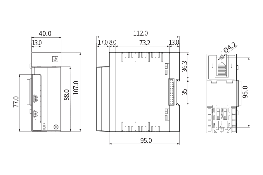
▍Specification
■ Range configuration by input type
|
Input type
|
Measuring range (℃)
|
Degree
|
|
Thermoresistor
(RTD)
|
Pt100 Ω
|
Pt-1
|
-200.0 ~ 640.0
|
±0.1 % of FS
±1 Digit
|
|
KPt100 Ω
|
KPt-1
|
-200.0 ~ 500.0
|
|
thermocouple
(TC)
|
K
|
K-0
|
-200 ~ 1370
|
±0.15 % of FS ±1 digit
|
|
K-1
|
-200.0 ~ 1370.0
|
±0.15 % of FS ±1 digit(*2)
|
|
J
|
-200.0 ~ 1200.0
|
±0.15 % of FS ±1 digit(*2)
|
|
E
|
-200.0 ~ 1000.0
|
±0.15 % of FS ±1 digit(*2)
|
|
T
|
-200.0 ~ 400.0
|
±0.15 % of FS ±1 digit(*3)
|
|
R
|
0.0 ~ 1700.0
|
±0.15 % of FS ±1 digit(*4)
|
|
B
|
0.0 ~ 1800.0
|
±0.15 % of FS ±1 digit(*1)
|
|
S
|
0.0 ~ 1700.0
|
±0.15 % of FS ±1 digit(*4)
|
|
L
|
-200.0 ~ 900.0
|
±0.15 % of FS ±1 digit(*2)
|
|
N
|
-200.0 ~ 1300.0
|
±0.15 % of FS ±1 digit(*3)
|
|
U
|
-200.0 ~ 400.0
|
±0.15 % of FS ±1 digit(*3)
|
|
Wre 5-26
|
0.0 ~ 2300.0
|
±0.15 % of FS ±1 digit(*4)
|
|
DC voltage
(VDC)
|
-10 - 20 mV
|
-10.00 ~ 20.00
|
±0.1 % of FS
±1 Digit
|
|
0 - 100 mV
|
0.00 ~ 100.00
|
|
1 - 5 V
|
1.00 ~ 5.00
|
|
0 - 30 V
|
0.00 ~ 30.00
|
- (*1) 0 ~ 400 ℃ : ±5 % of FS ±1 digit
- (*2) -200 ~ -150 ℃ : ±0.2 % of FS ±1 digit
- (*3) -200 ~ -150 ℃ : ±0.4 % of FS ±1 digit, -150 ~ -100 ℃ : ±0.2 % of FS ±1 digit
- (*4) 0 ~ 200 ℃ : ±0.2 % of FS ±1 digit
■ Power input
|
Power voltage
|
100 - 240 V a.c. Voltage regulation ±10 %
|
|
Power frequency
|
50 - 60 ㎐
|
|
Power consumption
|
30 VA max
|
|
Max. rating of internal fuse
|
250 V a.c.
|
|
Dielectric strength
|
Between 1st and 2nd terminals : Min. 1500 V AC for 1 min
Between 1st and FG terminals : Min. 1500 V AC for 1 min
Between 2nd and FG terminals : Min. 1500 V AC for 1 min
|
|
Insulation resistance
|
20 ㏁ or 500 V DC between power and FG terminals
|
■ Sensor input
|
Input type
|
2 types of RTD (Pt-100, KPt-100),
11 thermocouples (K, J, E, T, R, B, S, L, N, U, Wire 5-26)
4 types of DC voltage (-10 - 20 mV, 0 - 100 mV, 1 - 5 V, 0 - 30 V)
|
|
Sampling cycle
|
250 ms
|
|
Measured current of
thermoresistor(RTD)
|
Approx. 0.21 mA
|
|
Input resistance
|
thermocouple : 1 ㏁ or more, DC voltage : 1 ㏁ or more
|
|
Allowable wire resistance
|
RTD : MAX. 100 Ω/wire
(Except for RTDs in the range of -100.00 to 150.00, up to 10 Ω / wire)
Thermoresistor : 200 Ω or less
DC voltage : 2 ㏀ or less
|
|
Influence of wire resistance
|
RTD: ± 0.3 ° C / 10 Ω
(note that the wiring resistance of the three wires must be
the same)
|
|
Allowable input voltage
|
Thermocouple : ±10 V d.c. or less, DC voltage : ±33 V d.c. or less
|
|
Reference junction
compensation (RJC)
Temperature error
|
±1.5 ℃ (0 ~ 50 ℃)
|
|
Detection of sensor disconnection(Burn-out)
|
UP-Scale for disconnection
|
■ Output specifications
|
Contact output(DO)
|
Up to 32 relay
|
A Contact
|
30 V d.c. 3 A max, 250 V a.c. 3 A
|
|
B Contact
|
NO : 30 V d.c. 5 A max, 250 V a.c. 5 A
|
|
Control output
|
SSR output
|
ON : 18 V DC Pulse voltage (800 Ω or more load resistance)
|
|
SCR output
|
4 - 20 mA DC (600 Ω or less load resistance)
|
|
Transmission output
|
Current output
|
4 - 20 mA d.c.
|
|
Load resistance
|
600 Ω or less load resistance
|
|
Output limit
|
-5.00 - 105.00 %
|
|
Output type
|
Specific value(PV), Setting value(SV), Output(MV), and random
|
|
Refresh interval
|
250 ms
|
■ Contact input
|
Max. number of input
|
32 Contacts
|
|
Input type
|
No-voltage contact input
|
|
ON/OFF sensing resistor
|
Minimum 1㏀ and less: On, maximum 10㏀ and more: Off recognition
|
|
Min. sensing time
|
0.25 sec
|
|
Operational conditions
|
During operation/Always
|
|
Contact function
|
Operation and stop/hold/step by DI ; User can define error screen.
|
■ Communication specifications
|
Applied standard
|
RS485
|
|
Max. connection number
|
1:32 (address 1 ~ 99)
|
|
Communication type
|
2-wire
|
|
Synchronization
|
Asynchronous
|
|
Communication distance
|
Approx. 1.2 km or less
|
|
Communication speed
|
9600, 19200, 38400, 57600, 115200 bps
|
|
Data Length
|
7/8 bits
|
|
Parity Bit
|
NONE / EVEN / ODD
|
|
Stop Bit
|
1/2 bit(s)
|
|
Protocol
|
PC-Link / PC-Link+SUM / MODBUS ASC / MODBUS RTU
|
|
Response Time
|
0 - 100 ms
|
■ Control function
|
Input
|
Input calibration
|
EUS(0 ~ 100 %)
|
|
Input filter(LPF)
|
0 ~ 120 sec
|
|
Support chamber
|
type
|
Elevator type, damper type
|
|
Control operation
|
Pattern
|
Up to 100, Select the test type (10 types) for each pattern
|
|
PID Group
|
4 groups of high temperature room / low temperature room, deviation PID
|
|
Auto tuning
|
Auto tuning according to target setting value
|
|
Proportional band
|
0.00 ~ 100.00 % (For 0.00 %, ON/OFF control)
|
|
Integral time
|
0.0 ~ 3,000 sec (OFF when 0 sec)
|
|
Derivative time
|
|
ON/OFF control
|
Set 0.0 to proportional band(PB)
|
|
Normal Open/
Normal Close
|
According to selection of Normal Open/
Normal Close for control output
|
|
Prevent overloading
|
ARW zone setting
(50 to 1000% of proportional band)
|
|
A.T GAIN
|
0.0 ~ 10.0
|
|
Alarm setting
|
Alarm setting
|
System alarm : 8 points
|
|
Alarm type
|
Absolute high/low limit, deviation high/low limit, in range/out of range (alarm direction, hold)
|
|
Absolute alarm
setting range
|
EU(0 ~ 100 %)
|
|
Offset information
setting range
|
EUS(-100 ~ 100 %)
|
|
Hysteresis
|
EUS(0 ~ 100 %)
|
■ Display specifications
|
Display
|
TFT color LCD (115.2 x 86.4 mm)
|
|
Number of Pixels
|
640 x 480 pixel
|
|
Back light
|
LED Back light
|
|
Life cycle of back light
|
Approx. 40,000 h
|
|
Touch type
|
Resistive type (4 Wires)
|
|
Language
|
Korean/English/Chinese(Simplified)
|
■ Memory specifications
|
Internal memory
|
Non-volatile memory : 80 MB - Saving of 15 days at 1 S interval
|
|
External memory
|
SD card(2 GB) : Saving of 1 year at 1 S interval
|
|
Saving interval
|
1 ~ 360 sec
|
|
Memory information
|
Program information, setting value, recovery, and temperature setting/specific/output value
|
■ Use environment
|
Ambient temperature
|
0 ~ 50 ℃
|
|
Temperature fluctuation
|
10 ℃/h or less
|
|
Ambient humidity
|
20 ~ 90 % RH (Without condensation)
|
|
Magnetic field
|
400 A/m or less
|
|
Altitude
|
2,000 m or less from the sea
|
|
Weight
|
Approx. 1.32 kg
|
■ Storage environment
|
Ambient temperature
|
-20 ~ 70 ℃
|
|
Temperature fluctuation
|
20 ℃/h or less
|
|
Ambient humidity
|
5 - 95 % RH (Without condensation)
|
■ Influence of ambient temperature
|
DC voltage, Thermoresistor sensor
|
± 0.003% / ° C of maximum range
|
|
RTD sensor
|
±0.03 ℃/℃
|
▍Suffix code
|
Model
|
Code
|
Content
|
|
TS510-
|
|
|
|
Thermal shock test controller
|
|
Display section
|
1
|
|
|
Display section (5.7" TFT LCD)
|
|
N
|
|
|
None
|
|
Input•output
|
1
|
|
Input 16 points • Output 8 points (2 modules) + Power module + Control module
|
|
2
|
|
Inputs 16 points and output 16 points (3 modules) + Power module + control module
|
|
3
|
|
Inputs 16 points and output 24 points (4 modules) + Power module + control module
|
|
N
|
|
No input / output
|
|
Language
|
S
|
Korean, English, Chinese (simplified)
|
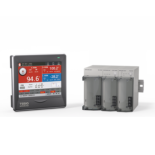
- This product basically consists of display part and control part (power module, control module,
input module, output module). (Up to 32 points of contact input configuration and up to 32
points of contact output configuration)
▍Dimension & panel cutout
|