▍Specification
■ Input specification
|
Input type
|
Thermocouple : K, J, E, T, R, B, S, L, N, U, W, PL2 (refer to input signal and measurement range)
RTD : Pt 100 Ω , KPt 100 Ω
DC voltage input : 1-5 V d.c., -10-20 ㎷, 0-100 ㎷ d.c., 4-20 ㎃ d.c.(250 Ω with external resistor)
|
|
Input sampling cycle
|
250 ms
|
|
Input display resolution
|
Basically, below the decimal point of the range
|
|
Input impedance
|
Thermocouple and DC voltage input (㎷) : min. 1 MΩ,
DC voltage input (V) : approx. 1 MΩ
|
|
Allowable signal source resistance
|
Thermocouple : max. 250 Ω ,
DC voltage : max. 2 kΩ
|
|
Allowable wiring resistance
|
RTD : max. 10 Ω /wire (conductor resistance among 3 wires should be the same)
|
|
Allowable input voltage
|
Within ±10 V (thermocouple, RTD, DC voltage : ㎷ d.c.)
Within ±20 V (DC voltage: V d.c.)
|
|
Noise reduction rate
|
NMRR (normal mode) : min. 40 dB (50/60Hz ±1 %)
CMRR (common mode) : min. 120 dB (50/60Hz ±1 %)
|
|
Standard
|
Thermocouple / RTD (KS/IEC/DIN)
|
|
RJC error
|
±1.5 ℃ (15 ~ 35 ℃), ±2.0 ℃ (0 ~ 50 ℃)
|
|
Input break detection
(BURN-OUT)
|
Thermocouple : OFF, UP/DOWN Scale selection
RTD : UP Scale (detection current at thermocouple and RTD BURN-OUT : approx. 50 nA)
|
|
Measurement accuracy
|
±0.5 % (FULL SCALE)
|
|
Input range
|
Refer to "Input Signal and Measurement Range"
Thermocouple, RTD : can be changed within the range of input signal and measurement range table.
DC voltage : min. and max. voltages can be changed within each range.
Scaling possible within the range of the measurement range.
|
■ Output specification
① Control output (output type can be selected from relay, current, SSR, heating
/ cooling type can be set individually.)
|
Relay contact output
|
Contact capacity : 240 V a.c. 3 A, 30 V d.c. 3 A (resistive load)
Contact configuration: 1C
Output operation : time proportion, ON / OFF
Proportional period : 1 to 1000 s
Output limit : high limit (OH) and low limit (OL) can be set in the range from 0.0 to
100.0%. Valid also for auto-tuning (AT).
ON / OFF Hysteresis : 0 to 100 % (full scale)
Time resolution : smaller between 0.1% or 10 ms
|
|
SSR output
(voltage pulse output)
|
ON voltage : NX2, 3, 4, 7, 9 approx. min. 12 V d.c. (load resistance min. 600 Ω ,
limited to 30 ㎃ in short circuit) OFF
voltage : max. 0.1 V d.c.
Proportional period : 1 ~ 1000 s
Output operation : time proportional
Output limit : high limit (OH) and low limit (OL) can be set in the range from 0.0 to
100.0%. Valid also for auto-tuning (AT).
Time resolution : smaller between 0.1 % or 10 ms
|
|
Current output
(4 - 20 ㎃)
|
Current output range : 4-20 ㎃ d.c.
Load resistance : max. 600 Ω
Accuracy : ±0.5 % of max. scale (4-20 ㎃ range),
Resolution : approx. 3,000
Output ripple : 0.3 % (P-P) or less of the maximum scale (150 Hz)
Output update cycle : 250 ㎳
Output operation : continuous PID
Output limit : high limit (OH) and low limit (OL) can be set in the range from -5.0 to
105.0 %. Valid also for auto-tuning (AT).
|
② Alarm output (HBA common)
|
Relay contact output
|
Contact capacity : 240 V a.c. 1 A, 30 V d.c. 1 A (resistive load).
Contact configuration : 1a
Output contacts : different according to model specifications (refer to wiring diagram)
|
|
Heater break alarm
|
1 EA (NX2, NX3, NX4, NX7, NX9)
Current measurement range: AC 1-50 A
(resolution: 0.5 A, ±5 % of maximum scale ± 1 digit).
Alarm output: set and use alarm output
Deadband: 0 ~ 100 % of max. range setting
Others: available for ON / OFF control or time proportional output (but not for
current output and cooling output).
When output is ON, the break can not be detected in less than 0.2 sec.
|
③ Retransmission output
|
Current output
|
Current output range : 0-20 ㎃ d.c., 4-20 ㎃ d.c.
Load resistance : max. 600 Ω
Accuracy : ±0.5 % of max 0 ㎃ or 4-20 ㎃ range
Resolution : approx. 3,000
Output ripple : max. 0.3 % (P-P) of the max. scale (150 Hz)
Output update cycle : 250 ㎳
|
■ Operating environment
|
Installation environment
|
Continuous vibration (5 - 14 Hz) : peak-to-peak max. 1.2 mm
Continuous vibration (4 - 150 Hz) : max. 4.9 m/s²
Short-time vibration : 14.7 m/s², max. 15 seconds (3 directions each)
Shock : 147 m/s², max. 11 ms (6 directions each 3 times)
Panel cutout : refer to "panel cutout"
|
|
Normal operating conditions
|
Ambient temperature : 0 ~ 50 ℃
Ambient humidity : 35 ~ 85 % RH (without condensation)
Magnetic field effect : max. 400 AT / m
Warm-up time : min. 30 minutes
|
|
Ambient temperature influence
|
Thermocouple, voltage input : ± 1 μV / ℃ or ± 0.01 % / ℃ of max. range
RTD input : max. ± 0.05 Ω / ℃
Analog output : max. ± 0.05 % / ℃ of max. range (continuous output)
|
■ Power specification
|
Power voltage
|
100-240 V a.c.
(voltage fluctuation rate : ±10 %)
|
24 V a.c. / V d.c.
|
|
Power frequency
|
50 / 60 Hz
|
|
Power consumption
|
Max. to 6.0 W, max. 10 VA, 8 VA (NX1)
|
|
Insulation resistance
|
1st terminal - 2nd terminal : min. 500 V d.c. 20 MΩ
1st terminal - ground : min. 500 V d.c. 20 MΩ
2nd terminal - ground : min. 500 V d.c. 20 MΩ
|
|
Dielectric strength
|
1st terminal - 2nd terminal : 2,300 V a.c. 50/60 Hz for 1 min.
1st terminal - ground : 2,300 V a.c. 50/60 Hz for 1 min.
2nd terminal - F•G : 1,500 V a.c. 50/60 Hz for 1 min.
|
|
Sensor power supply
|
12 V d.c.(20 ㎃ d.c., cannot be used with retransmission output)
|
■ Transport and storage conditions
|
Storage temperature
|
-25 ~ 70 ℃
|
|
Storage humidity
|
5 ~ 95 % RH (without condensation)
|
|
Shock
|
Max. 1 min packaging
|
■ Input signal and measuring range
※ CAUTION
-
Measuring input wiring
- When wiring the measuring input line, disconnect the controller body and external power
supply to avoid a danger of electric shock.
- Pay attention to the polarity of the input before connecting. Wrong connection
may result in malfunction.
- Use shielded wires for input wiring. The shield must be grounded at
single-point.
- For measuring input signal, wire after leaving room between the power supply circuit
and the ground circuit, if possible.
|
Input signal
|
Selection number
|
Input type
|
Range (℃)
|
Accuracy
|
Remarks
|
|
Thermocouple
(TC)
|
1
|
K
|
*2
|
-200 ~1370
|
±0.5 % of FS ± 1digit
|
• FS is from the minimum to the maximum value of each measurable range.
• Digit is the minimum display value
※1
0 ~ 400 ℃ range: ± 10.0 % of FS ± 1 digit
※2
Below 0 ℃: ± 1.0% of FS ± 1 digit
※3
20 → KPt100 Ω (C1603)
※3
21, 22 → Pt100 Ω (IEC751)
※4
When current input is used, attach a 250Ω 0.1 % resistor to the input signal terminal.
|
|
2
|
K
|
*2
|
-199.9 ~ 999.9
|
|
3
|
J
|
*2
|
-199.9 ~ 999.9
|
|
4
|
E
|
*2
|
-199.9 ~ 999.9
|
|
5
|
T
|
*2
|
-199.9 ~ 400.0
|
|
6
|
R
|
0 ~ 1700
|
|
7
|
B
|
*1
|
0 ~ 1800
|
|
8
|
S
|
0 ~ 1700
|
|
9
|
L
|
*2
|
-199.9 ~ 900.0
|
|
10
|
N
|
-200 ~1300
|
±1.0 % of FS ± 1 digit
|
|
11
|
U
|
*2
|
-199.9 ~ 400.0
|
±0.5 % of FS ±1 digit
|
|
12
|
W
|
0 ~ 2300
|
|
13
|
Platinel II
|
0 ~ 1390
|
|
RTD
(RTD)
|
20
|
KSPt100 Ω
|
*3
|
-199.9 ~ 500.0
|
±0.5 % of FS ±1 digit
|
|
21
|
Pt100 Ω
|
*3
|
-199.9 ~ 640.0
|
|
22
|
Pt100 Ω
|
*3
|
-200~640
|
|
DC voltage
(V d.c./㎷ d.c.)
|
30
|
1-5V d.c.
|
-1999 ~ 9999
(Using the scaling function
(SL-H / SL-L))
|
±0.5 % of FS ±1 digit
|
|
31
|
0-10 V d.c.
|
|
32
|
-10-20 ㎷ d.c.
|
|
33
|
0-100 ㎷ d.c.
|
|
Direct current
|
30
|
4-20 ㎃ d.c.
|
*4
|
▍Model code
■ NX1 model code
Model |
Code |
Content |
NX1 - |
|
|
Multi Input/Output Temperature Controller. 48(W) X 24(H) ㎜ |
Control type |
0 |
|
Normal type |
1 |
|
Heating/cooling control (simultaneous control) |
Normal type |
|
Options |
Terminal number ④,⑤ |
Terminal number ⑥,⑦ |
Default |
0 |
RET |
RET |
0UT1 (RLY) |
3 |
1 |
- |
0UT1 (SSR/SCR) |
- |
1 |
2 |
RS485/RET |
RET |
0UT1 (RLY) |
3 |
3 |
RS485 |
0UT1 (SSR/SCR) |
- |
1 |
4 |
ALM |
0UT1 (SSR/SCR) |
ALM |
1 |
5 |
RS485/ALM |
0UT1 (SSR/SCR) |
ALM |
1 |
Heating/cooling type |
0 |
- |
0UT2 (SSR/SCR) |
0UT1 (RLY) |
6 |
1 |
- |
0UT1 (SSR/SCR) |
0UT2 (RLY) |
10 |
2 |
RS485 |
0UT2 (SSR/SCR) |
0UT1 (RLY) |
6 |
※ OUT1: Heating output, OUT2: Cooling output
■ NX1 control output configuration
Type |
Output |
Heating |
Cooling |
RELAY ⑥-⑦ |
SSR/SCR ④-⑤ |
RELAY ⑥-⑦ |
SSR/SCR ④-⑤ |
Normal type |
0 |
RLY (0N/0FF) |
RET |
- |
1 |
ALARM |
SSR |
2 |
SCR |
3 |
RLY |
RET |
Heating/Cooling type |
6 |
RLY |
- |
- |
SSR |
9 |
- |
- |
SCR |
10 |
- |
SSR |
RLY |
- |
11 |
- |
SCR |
- |
※ RLY (Relay output), SSR (Voltage pulse output), SCR (Current output, 4-20mA d.c.), RET (Retransmission output)
■ NX2, 3, 7, 9 model code
Model |
Code |
Content |
Default |
NX |
- |
|
|
Multi Input/Output Temperature Controller |
|
Size |
2 |
|
|
48 (W) X 96 (H) mm |
|
3 |
|
|
96 (W)X 48 (H) mm |
|
7 |
|
|
72 (W) X 72 (H) mm |
|
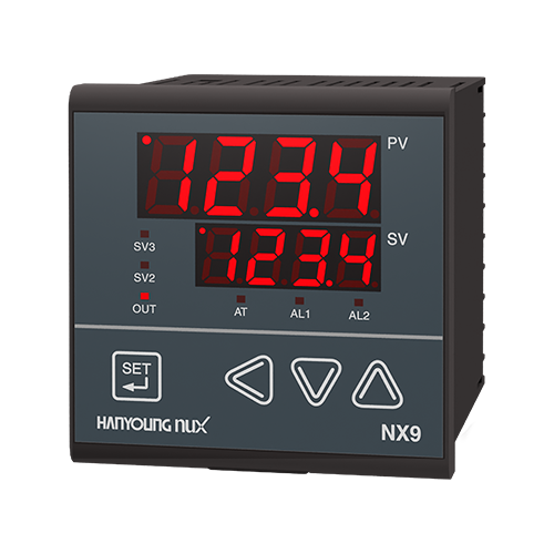
9 |
|
|
96 (W) X 96 (H) mm |
|
Control method |
0 |
|
Normal type (heating control) |
1 |
1 |
|
Heating/cooling (simultaneous) control |
4 |
NX9 option |
0 |
None |
|
1 |
RS485, HBA |
|
NX7 option |
0 |
None |
|
1 |
RS485, HBA |
|
2 |
SV2, SV3, HBA |
|
NX2, NX3 option |
0 |
SV2, SV3 |
|
1 |
HBA |
|
2 |
RS485 |
|
■ NX2,3,7,9 control output configuration
(if the control output is SCR, HBA cannot be used.)
Type |
Output |
Heating |
Cooling |
RELAY |
SSR/SCR/RET |
RELAY |
SSR/SCR/RET |
Normal type |
0 |
RLY (0N/0FF) |
- |
AL2 |
RET |
1 |
- |
SSR |
2 |
SCR |
3 |
RLY |
- |
Heating / Cooling type |
4 |
- |
SSR |
AL2 |
SSR |
5 |
SCR |
6 |
RLY |
RET |
7 |
- |
SSR |
SCR |
8 |
SCR |
9 |
RLY |
RET |
10 |
- |
SSR |
RLY |
RET |
11 |
SCR |
12 |
RLY |
- |
※ RLY (Relay output), SSR (Voltage pulse output),
SCR (Current output, 4-20mA d.c.), RET (Retransmission output)
■ NX4 model code
Model |
Code |
Content |
Remarks |
NX4 |
- |
|
Multi Input/Output Temperature Controller 48(W) X 48(H) ㎜ |
|
Control method |
0 |
|
Normal type (heating control) |
|
1 |
|
Heating/cooling control (simultaneous control) |
Default = 1 |
2 |
|
Heating/cooling control (NX4-20 only) |
Default = 4 |
NX4-0□ |
0 |
None |
|
1 |
HBA, AL2 |
OUT1 (terminals①-②-③) applied as AL1.
(when selecting SSR / SCR control output)
|
2 |
SV2, SV3 |
|
3 |
RET, RS485 |
|
4 |
RS485 |
|
5 |
AL1, AL2 |
|
6 |
AL1, AL2, SV2 |
OUT1 (terminals⑥-⑦)applied as SV2
(when selecting RELAY control output)
|
7 |
RS485, HBA |
|
NX-4-1□ |
0 |
None |
OUT2 (terminals⑪-⑫) applied as SSR/SCR. |
4 |
RS485 |
NX-4-2□ |
0 |
AL1 |
OUT2 (terminals⑪-⑫) applied as RLY. |
※ OUT1(①-②-③) can be used for AL1 when AL1 is not selected.
※ OUT1: Heating control, OUT2 : Cooling control
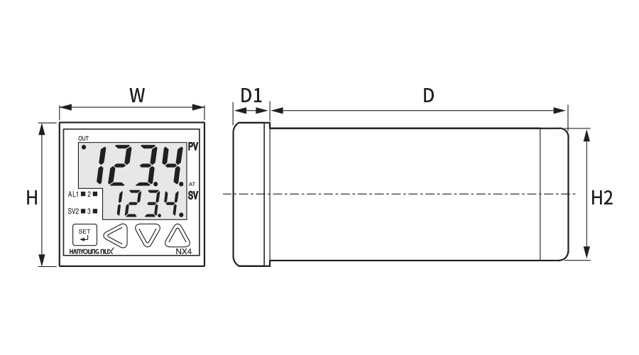
▍Dimension and panel cutout
■ Dimension
| Classification |
Type |
NX1 |
NX2 |
NX3 |
NX4 |
NX7 |
NX9 |
Product
dimensions |
W |
48.0 |
48.0 |
96.0 |
48.0 |
72.0 |
96.0 |
| H |
25.5 |
96.0 |
48.0 |
48.0 |
72.0 |
96.0 |
| H2 |
22.0 |
91.0 |
44.8 |
44.8 |
66.0 |
91.0 |
| D |
100.0 |
100.0 |
100.0 |
100.0 |
100.0 |
100.2 |
| D1 |
5.8 |
12.5 |
12.5 |
7.4 |
12.5 |
12.5 |
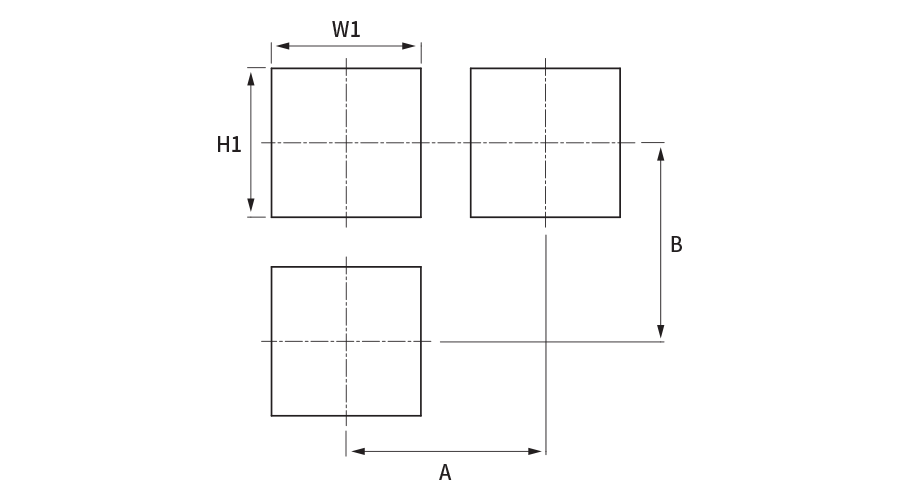
■ Panel cutout
| Classification |
Type |
NX1 |
NX2 |
NX3 |
NX4 |
NX7 |
NX9 |
Panel cutout
*1) |
W1 |
45.0 |
45.0 |
92.0 |
45.0 |
68.0 |
92.0 |
| H1 |
22.4 |
92.0 |
45.0 |
45.0 |
68.0 |
92.0 |
| A |
65.0 |
70.0 |
122.0 |
60.0 |
93.0 |
117.0 |
| B |
42.4 |
122.0 |
70.0 |
60.0 |
93.0 |
117.0 |
|
*1) +0.5 mm tolerance applied
|
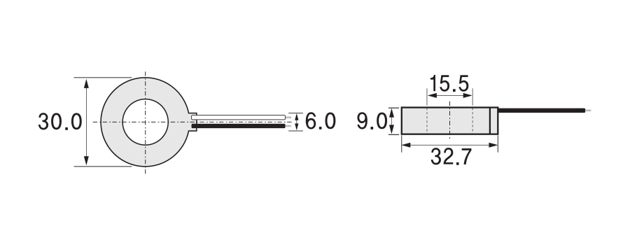
■ Current detector (Model name: CT-50N) ※ Sold separately
|