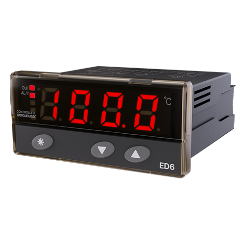

- Cooling control and heating control selection
- Alarm output and timer output selection
- ON/OFF and proportional control selection
- 0.1 ℃ / 1 ℃ selection
- Delay output time setting
Suffix codeDimensionPart nameConnection diagramControl method for temperatureProportional controlDelay Timer SettingAuxiliary output set and operating descriptionOutput capacity and set value verification modeUser setting modeInstaller setting modeAdministrator setting mode
The order from the left is the order in which the information is displayed at the bottom.
If you cancel the check, the information will be excluded, and if you check, it will be
printed out.
▍Specification
everyone
Voltage
AC power type
100 - 240 V ~ 50/60 Hz
DC power type
10 - 24 V d.c., Class2
voltage change rate
± 10 % of supply voltage
Consumption
power
AC power type
10.0 VA or less
DC power type
2.0 VA or less
Input
K, Pt 100 Ω, 4 - 20 mA d.c., 1 - 5 V d.c.
Indicate accuracy
± 0.5 % of FS ± 1 Digit
Control output
Relay
Contact setup : 1 c, 250 V a.c., 5 A (resistive load)
SSR
10 - 15 V d.c. (Load resistance 500Ω or more), Approx. 20 mA V d.c. Max
Alarm/Defrost
Relay
Contact setup : 1 c, 250 V a.c., 5 A (resistive load)
Control acting
Reverse acting (heating) or direct acting (cooling)
Setting method
Digital type manipulated by setting, increase and decrease buttons
Additional features
Alarm & Defrost
Wire resistance
Thermocouple
Below 100 Ω round trip.
R.T.D
Below 10 Ω for each wire (Resistance of 3 wires should be the same.)